Ceramic Capacitor Characteristics: Pay attention to C(V)
Introduction
During electronics design reviews, it’s overwhelmingly common to find changes are needed for basic bypass and DC storage caps due to ignoring the C(V).
The Voltage Rating is the maximum operating voltage that doesn’t risk (immediate) damage.
C(V) refers to the the change in capacitance with DC bias (voltage).
For high-density capacitors, the capacitance drop is frequently near 90% at the rated voltage. If this isn’t designed around then it can lead to instability, brownouts, and excess noise.
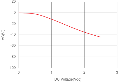
50% drop in capacitance with a 330uF 1210 X6S MLCC.
The 330uF cap shown has a voltage rating of 2.5V and loses 50% of the capacitance at the rated voltage which actually isn’t bad going for such high density.
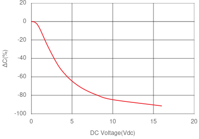
90% drop in capacitance for a 1uF 0201 X5R MLCC.
This 1uF X5R component is down to 10% of its capacitance at the rated voltage.
Some dielectrics perform significantly better. C0G/NP0 types exhibit virtually no change in capacitance with DC bias. Their downside is a lower epsilon so a lower density.
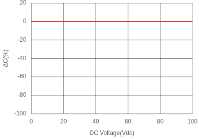
Stable NP0/C0G response. 10nF NP0 0603 C(V) curve showing no change.
Choosing a cap without checking the characteristic curves is a recipe for mysterious problems later in the design or production. It used to be that getting the characteristics data was a chore. The curves were not included in the data sheets but rather in a separate characteristics sheet. Now however most large manufacturers have introduced webapps that let you lookup the characteristic instead of needing to dig around for a PDF. Note that most of these suppliers also have spice models for their parts for when the selection really matters.
- Murata: simsurfing
- Samsung: Product Search
- TDK: Product Center
- Kyocera / AVX: SpiLMCC
- Taiyo Yuden: TY-Compas
- Kemet / Yageo: KSim
Certainly improves the parts selection experience!