KiCad Coordinate System
Categories:
The KiCad coordinate system can be unintuitive, especially when scripting or developing plugins. Here’s what I learned while building the JigsApp system and the kicad-testpoints plugin.
The origin and axis settings are global display preferences for the PCB editor (pcbnew) and can be accessed from all of the KiCad programs (eeschema, project, pcbnew, Symbol Editor, Footprint Editor, Gerber Viewer, Image Converter, Calculator Tools, Drawing Sheet Editor, and 3D Viewer).
The origin type and axes settings can only be changed for the PCB Editor.
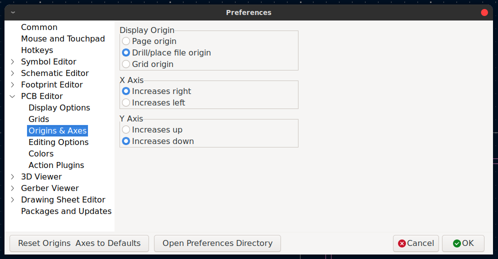
KiCad 8 Origin & Axes Preferences
These settings only change the mapping that shows up in the editor. The origin positions (grid and drill/file/aux) are stored in the PCB file but the mapping preferences are not. This can be confusing when using different instances of KiCad that aren’t configured the same way.
Origins
There are three types of origins in KiCad:
- Page Origin: Top left corner of the page. This is the default and is the internal coordinate system. This is the point vectors are relative to in the python API.
- Drill/File (AKA Aux) Origin: Sets the origin for file exports like drill and pick-and-place. It doesn’t affect object placement in the editor or scripting. KiCad still uses the Page Origin for those. The marker for this is a red cross in a circle.

Drill/File Origin Marker
- Grid Origin: Sets the starting point of the grid and only effects the grid snapping not the exported data. This typically stays constant once the design has started. This is normally the same as the drill origin (if placed). The marker is a grey x in a circle.

Grid Origin Marker
Axes
Internally (and by default) the axes follow a pixel coordinate system where the origin is in the top left with x increasing to the right and y increasing downwards.

Pixel coordinate system. Source: adafruit.com

Cartesian coordinate system. Source: wikipedia.com
Gerbers and pick-and-place (centroid) files use a Cartesian coordinate system—origin at the bottom-left, Y increasing upwards. KiCad’s editor uses a pixel-style system by default—origin at the top-left, Y increasing downwards. This mismatch can lead to mirrored placements or flipped values if not handled correctly. The place I find this most infuriating is the centroid file (A.K.A. component placement or pick-n-place). If we export the centroid then use that to place the parts either manually or naively with a script then the placement will be mirrored!
The axes directions can be changed in the same preference window as the origin point but this won’t change the internal position. When writing a script then this needs to be kept in mind.
Preferences
The PCB Editor is the only program that you can set the origin or axes direction in and these preferences are not exposed to the Python API. If you change your axes and origin in the PCB Editor you’re still using the pixel coordinates in the footprint editor!
Scripting
I prefer to refer to the origin of a board as the reference point (see the post here discussing using board outlines as footprints). This is usually the center of the boards bounding box but it may be the center of a sensor (e.g. a photodiode) or an emitter (ex. a laser diode). In the design I place the drill origin where it needs to go (usually placing it at the center of the board which is implemented as a footprint, so it has a snap-to-center point.). I keep everything in Cartesian coordinates relative to the origin and multiply the Y value by –1 when needed to match KiCad’s internal (pixel-style) coordinate system.
For my KiCad plugins I’ll be adding the option to use the drill/file/aux origin or the page origin and limit the axes to Cartesian coordinates.
Transforming Coordinates
For an arbitrary origin point
$$ \text{origin} == (x_0, y_0) $$and a pcbnew location
$$ \text{pt} == (x, y) $$we want the mapped location to the new coordinates
$$ \text{pt'} == (x', y'). $$Since we want the opposite direction in y and the same in x:
$$ x' = x - x_0 $$$$ y' = y_0 - y. $$To transform back:
$$ x = x' + x_0 $$$$ y = y_0 - y'. $$If your origin position is set to the page origin then all the y’ values are going to be negative. Transform to native KiCad coordinates when setting positions and back when reading them. The user setting of the axes will not effect the outcome.
Suggestions List
- Use Cartesian coordinates: X increases right, Y increases up. This matches EDA exports and manufacturing conventions.
- Use Cartesian coordinates and delay conversion to KiCad’s internal system until the final step in scripting.
- Choose a well-defined reference point on your board (e.g., board center, sensor center) and set that as the drill/file origin.